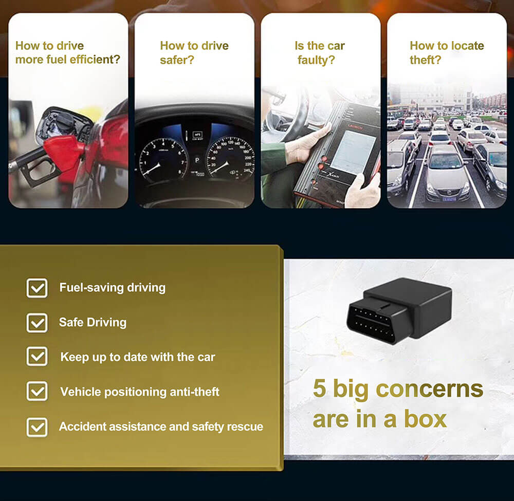
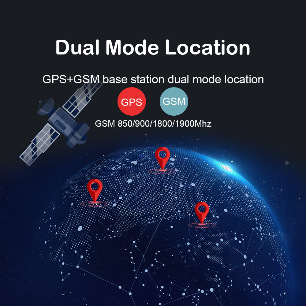
Roadragon has designed a vehicle anti-theft system based on NB-IOT, which mainly uses NB-IOT wireless communication technology, GPS and Beidou dual-mode positioning technology to address the current public security problems of frequent theft of bicycles and electric motorcycles. The overall solution for the investigation after the case is reached.
With the promotion of the concept of low-carbon travel in recent years, the use of high-end bicycles, electric vehicles, and motorcycles has increased, and the subsequent stolen and difficult-to-track vehicles have become a major problem that plagues many car owners. However, the common vehicle anti-theft solutions on the market still have many defects[1]:
(1) 2G solution: 2G is reducing capacity and retiring from the network, with weak coverage, poor signal, no signal in underground parking lots, and high power consumption.
(2) RFID solution: The vehicle is generally more than ten meters away from the pole of the RFID reader, the signal is very weak, the data cannot be read, and the terminal is disconnected; the vehicle cannot be located or tracked in the county or rural area, and the urban area is limited to key crossings; Road pole readers must be inspected and maintained frequently.
Aiming at the shortcomings of the above two schemes, this paper designs an intelligent vehicle anti-theft system based on NB-IOT, which has the advantages of wide coverage, large connections, and low power consumption.
1 System architecture
The intelligent anti-theft system based on NB-IOT mainly includes three parts: equipment terminal , background processing system and user terminal. The system terminal sensor can be connected to the operator’s IO domain intranet through NB-IOT. The background application system supports the docking of public security network interactive case data. The user can monitor the vehicle through the mobile phone, and the background management system can maintain the overall user data. Management and monitoring.
2 Overall plan
This system transfers the GPS&Beidou satellite dual-mode positioning data and the state value of the vibration sensor to the single-chip STM32, which is then uploaded to the core network through the NB-IOT communication module, and transmitted to the cloud platform through the HTTPS protocol, and then through the cloud transparent transmission function, It is forwarded to the cloud server, then stored to MySQL and transmitted to the APP on the mobile phone.
3 System hardware design
The hardware equipment of this system mainly includes vehicle status detection module, GPS & Beidou satellite dual-mode positioning module and NB-IOT communication module, STM32 single-chip microcomputer control module. The system hardware framework is shown in Figure 2. The function of the vibration state detection module is to detect the state of the vehicle and whether there is any movement of the vehicle. The function of the GPS&Beidou satellite dual-mode positioning module is to locate the position of the vehicle, obtain the latitude and longitude value, and transmit it to the single-chip STM32. NB
The function of the IOT communication module is to send the vehicle status collected by the sensors and the positioning information resolved by the main control chip to the IoT cloud platform. As the main control chip, the STM32 microcontroller is the core part of the system hardware. Its function is to implement the underlying functions of the system through code, such as obtaining the longitude and latitude data of the GPS& Beidou satellite dual-mode positioning through the serial port interrupt and detecting whether the vibration sensor inputs a high level , Pack the acquired data and upload it to the cloud server through the NB-IOT module. At the same time, it also receives the instructions issued by the mobile phone APP to determine whether the anti-theft mode should be turned on.
3.3 Analysis of experimental results
It can be seen from Figure 2 that in the different hyperparameters Agent1~4, the vehicle flow in the Agent1, Ag ent2, and Agent3 phases is controlled at 600 veh/h, while the vehicle flow in the Agent4 phase is controlled at 500-600 veh/h. This setting It can effectively guarantee the diversity and randomness of test scenarios. Among them, the signal status in the agent traffic network can be represented by the length of the waiting queue at the intersection; the action function to maximize the accumulated reward value can be represented by the absolute value of the difference between the east-west and north-south waiting queue lengths. The experimental results show that, compared to the neural network function value of Agent1 and Agent2, Ag
The performance of ent3 and Agent4 in urban traffic signal control is more stable, and the overall average speed of Agent4 is larger and the average waiting queue length is smaller, which is better than Agent1, Agent2, and Agent3.
Conclusion
Based on the SCATS system, our country proposes a deep reinforcement learning algorithm for the traffic agent (Agent) based on the city’s complex traffic signal control network to collect, model and analyze traffic flow data at different times, including the location of urban vehicles. , Global traffic speed, average waiting queue length and other data simulations, the obtained urban traffic signal control results are more stable. Through the optimization of different timing parameters and the selection of green letter ratio schemes, it can meet the signal control needs of intersection traffic at different times.
4 System software design
The software design of this system includes STM32 control module [2], GPS & Beidou dual-mode positioning module, NB-IOT data communication module. As shown in the system software flowchart 3, the device terminal system is powered on, the peripheral hardware circuit and the NB-IOT communication module are initialized, and then it is connected to the IoT cloud platform. If the connection is not successful, wait a few seconds before reconnecting. The sending interval is 5 seconds. If the time interval is greater than 5 seconds, the positioning data will be obtained, the positioning information will be sent to the cloud platform, and the counter will be cleared, then the platform return data will be obtained, if the return data is not empty, the detection data will be performed, and then the loop will be entered In the body, continue to obtain and send location information.
4.1 Software design of STM32 control module
The STM32 control module uses the initialization function to set the preemption priority and response priority of the serial port and external interrupt pins. The serial port is responsible for receiving GPS data and sending and receiving data from the NB-IOT module, and the external interrupt pin detects the level input of the shock sensor.
4.2 GPS & Beidou dual-mode positioning module software design
First set the Beidou positioning module to the measurement mode, then obtain the Beidou positioning data, calculate the Z-axis angle, and then set the Beidou positioning module to the standby mode, and return to the main function interrupt position. Enable the serial port receiving terminal and configure its interrupt priority. The serial port interrupt processing function receives the data sent by the GPS&Beidou dual-mode positioning module and analyzes the required latitude and longitude values from it.
4.3 NB-IOT data communication module software design
The NB-IOT communication [4] module uses the AT command to indict, the communication module initialization sub-function configures the NB-IOT parameters, sets the NB-IOT to CMD mode, and sets the IP address and port number of the cloud transparent transmission. The serial data received by NB-IOT STM32 is uploaded to the cloud server through HTTPS protocol. Data transmission is to send messages in hexadecimal format, and receive and execute instructions through the serial port processing function to achieve data reception.
4.4 User terminal design
The overall framework of the user terminal is shown in Figure 5. The user side of this system uses the WeChat web developer tool to develop WeChat applets. The user terminal software part mainly includes logging in user information, accessing user equipment, obtaining user equipment data, and displaying user equipment data Wait for four parts.
5 System test and analysis
This system is powered by a lithium battery and has an external power supply voltage: 12V-40V, working temperature: 40°C~70°C, humidity: <95% RH, support frequency band LTE-FDD B3/B5/B8, LTE-M1 , LTE-NB1.
5.1 System software function test
Through field measurement, when the vehicle moves, an alarm is triggered and the alarm information is uploaded to the cloud. The system can locate vehicle information in real time, as shown in Figure 6; when the vehicle vibrates, it will give an alarm of abnormal vehicle vibration, as shown in Figure 7; and the mobile phone can view the corresponding alarm information.
6 Conclusion
The intelligent vehicle anti-theft system designed in this paper adopts NB-IOT technology to realize wireless data transmission, which can ensure the speed and quality of data transmission, and has a wider coverage; it adopts GPS & Beidou dual-mode positioning system, which can still be used after the vehicle is stolen. See the real-time location of the vehicle from the mobile terminal, so as to quickly find the stolen vehicle, which provides an effective means for prevention before the case and investigation after the case.
Post time: Sep-18-2020


